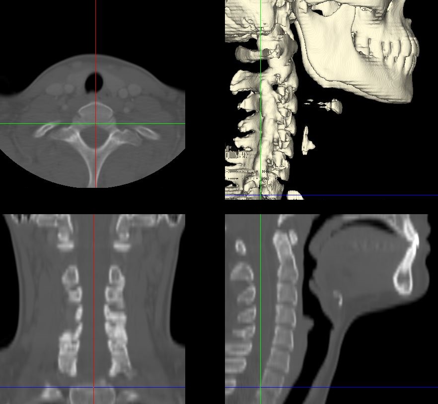
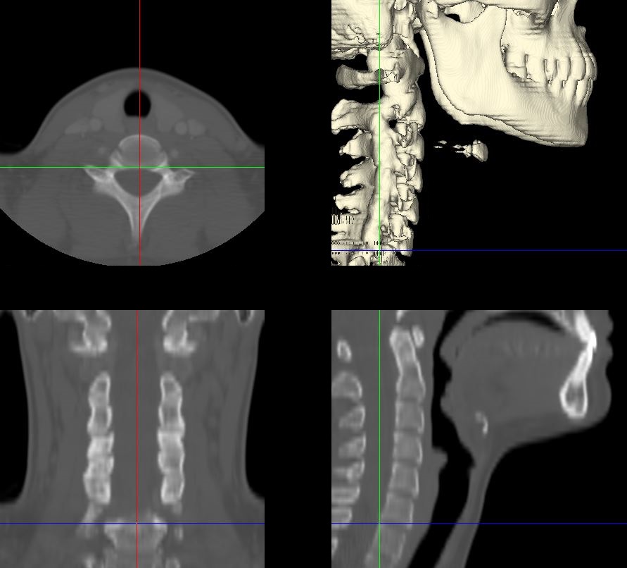
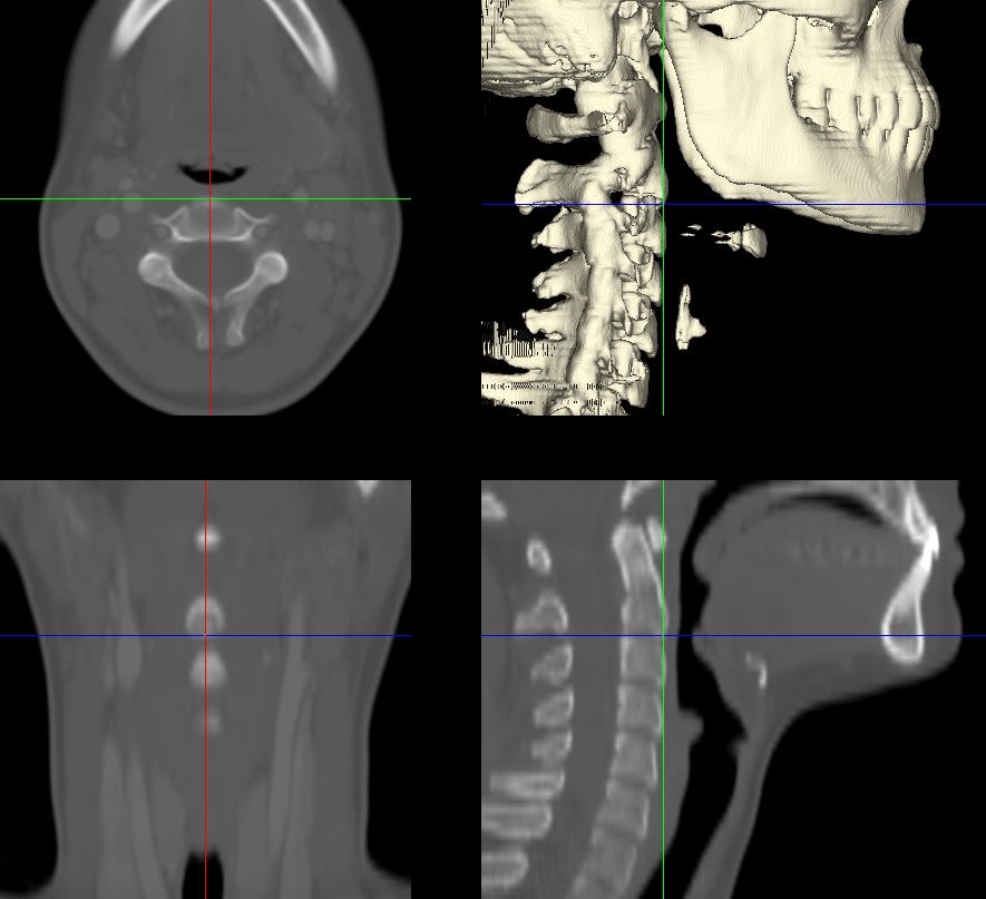
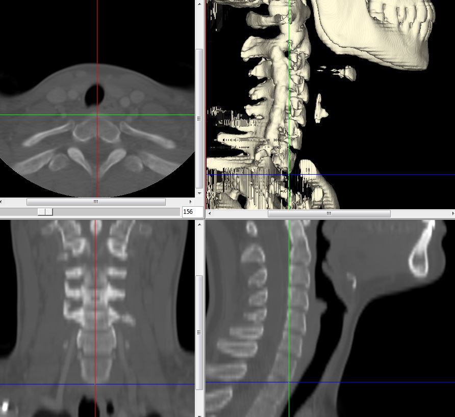
Data collection for Head Position Protocol
The head position protocol requires 14 landmarks placed on medical imaging studies rendered in 3D. During the development of this protocol, the landmarks were acquired using Analyze 12.0. Each landmark should provide (x,y,z) coordinates and the voxel size should be recorded for each imaging study.
The landmarks are used to calculate 17 measurements. These 17 measures are then used in two hybrid GUIDE forest prediction models to classify head position.
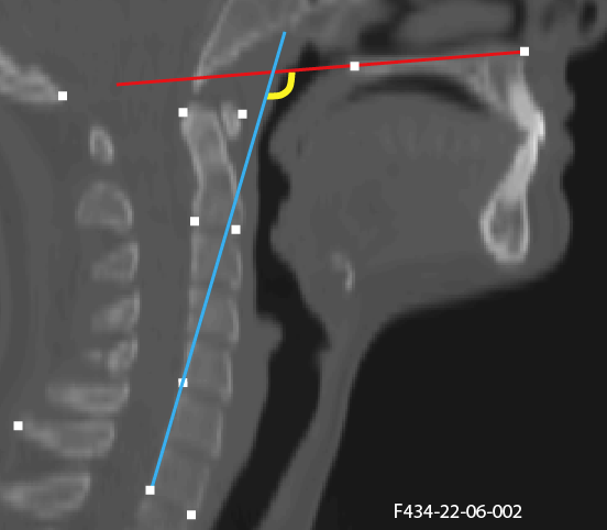
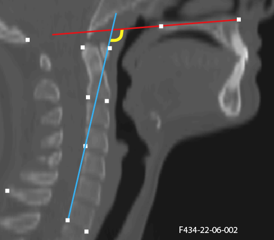
Landmarking Protocol

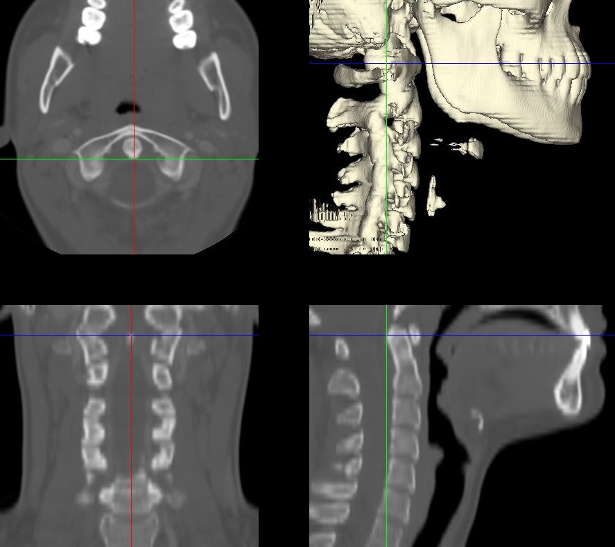
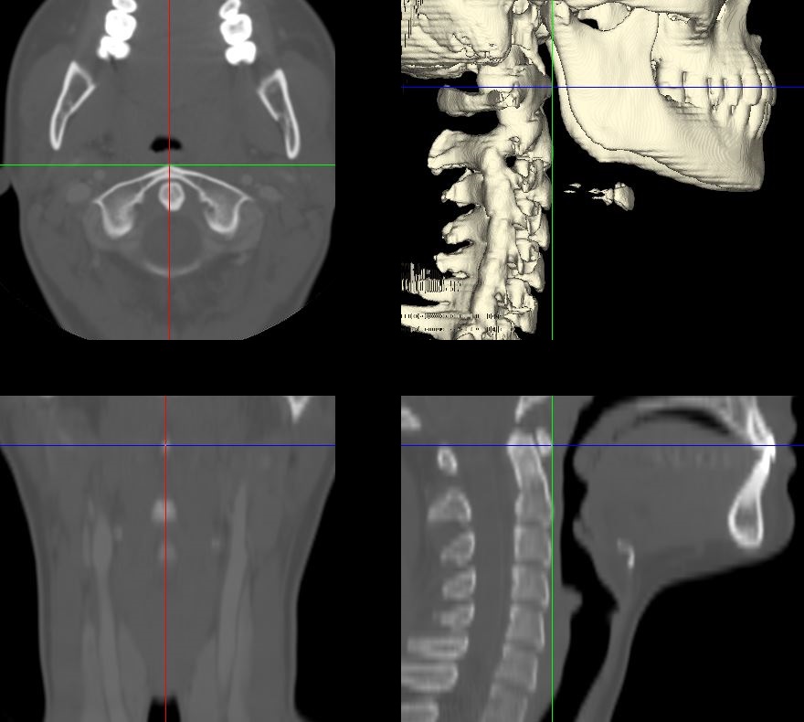
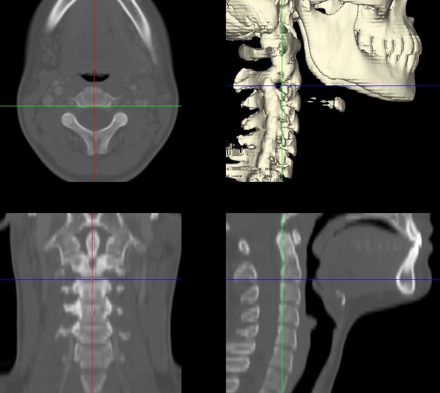
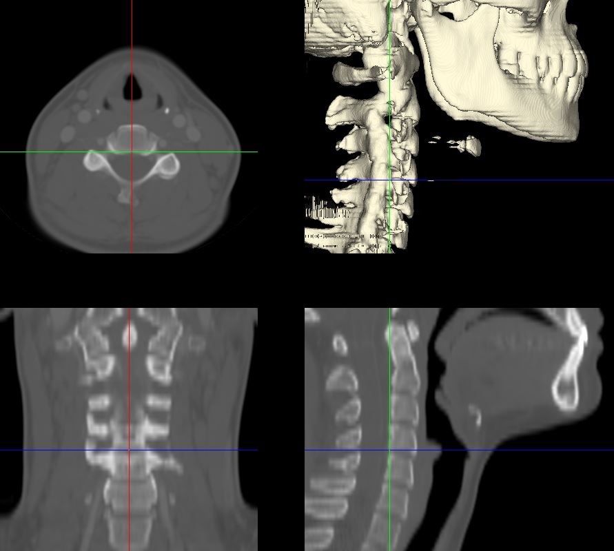
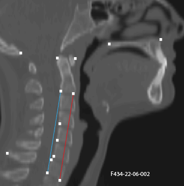
This figure vizualizes all the landmarks necessary to classify head position. Each landmark should be placed in the anatomical midsagittal point defined for each landmark. These landmarks are used in combination to calculate the measurements described below.
1. Anterior Nasal Spine (ANS)

The first landmark is placed at the most anterior point of the nasal spine.
2. Posterior Nasal Spine (PNS)

The second landmark is placed at the most posterior point of the nasal spine.
3. Opisthion (OPI)

The third landmark is placed at the most anterior-inferior point on the posterior margin of the foramen magnum.
4. Spinous Process of C7 (SpPro7)

The fourth landmark is placed at the most posterior point on the spinous process of C7. In the case of bifid spinous processes, the landmark should be placed on the midpoint of where the two sides deviate, instead of the exact most posterior aspect.
5. Posterior Superior corner of the apex of the axis, C2 (PSA)
The fifth landmark is placed at the most posterior and superior conrner of the apex of the odontoid at the anatomical midline. This landmark should be placed at the superior corner of the posterior border of C2.
6. Anterior Tubercle of Atlas, C1 (AT1)
The sixth landmark is placed at the most medio-anterior point of C1 denoting the anterior tubercle of the atlas, C1.
7-11. Posterior Inferior Margin of vertebral body
For C2 and C4 to C7, place the landmarks on each vertebrae at the most posterior and inferior point of the vertebral body.
C2
The seventh landmark is placed at the most posterior and inferior point of the C2 vertebral body in the anatomical midsagittal plane.
C4
The eight landmark is placed at the most posterior and inferior point of the C4 vertebral body in the anatomical midsagittal plane.
C5

The ninth landmark is placed at the most posterior and inferior point of the C5 vertebral body in the anatomical midsagittal plane.
C6

The tenth landmark is placed at the most posterior and inferior point of the C6 vertebral body in the anatomical midsagittal plane.
C7
The eleventh landmark is placed at the most posterior and inferior point of the C7 vertebral body in the anatomical midsagittal plane.
12. Posterior Superior Margin of C7 vertebral body
The twelfth landmark is placed at the most posterior and superior point of the C7 vertebral body in the anatomical midsagittal plane.
13-14. Anterior Inferior Margin of C2 and C7 vertebral bodies
For C2 and C7, place the landmarks on each vertebrae at the most anterior and inferior point of the vertebral body.
C2
The thirteenth landmark is placed at the most anterior and inferior point of the C2 vertebral body in the anatomical midsagittal plane.
C7
The fourteenth landmark is placed at the most anterior and inferior point of the C7 vertebral body in the anatomical midsagittal plane.
Measurements
This protocol utilizes 17 measurements to quantify head position. These measures assess both the face plane and the neck position.
Head Measures or Face Plane Measures
V1. ANS-PNS Plane
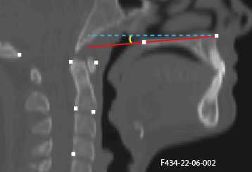
The angle of the nasal spine plane defined by the anterior nasal spine (ANS, 1) and the posterior nasal spine (PNS,2) landmarks subtended with the horizontal plane of the imaging study.
V2. Maxillo-Pharyngeal (MP) Angle
The angle of intersection between the PNS (2) - anterior tubercle of C1 (AT1, 6) line and the AT1 (6) - anterior inferior point of C2 (C2ai, 13) line.
V5. Modified Bhalala head tilt angle
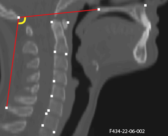
The angle of intersection between the PNS (2) - opisthion (OPI, 3) line and the OPI (3) - C7 spinous process (4) line.
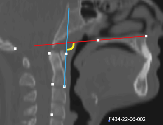
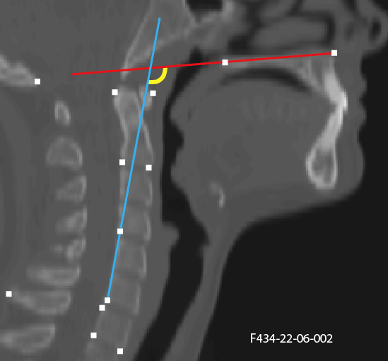
V7. C2 Angle
The angle of intersection between the posterior border of C2 (7, 5) line and the ANS (1) - PNS (2) plane.
Neck Measures
Antero-Posterior Measures
The anterior and posterior distances are calculated between the inferior landmarks of C2 to C7 and used for two of the head position measures. To ensure the distance measurements are calculated in millimeters (mm), the coordinates should be multiplied by the voxel size of each imaging study.
V3. Antero-Posterior Distance Ratio
The ratio of the anterior to the posterior distances from the inferior borders of C2 to C7.
V4. Antero-Porsterio Distance Difference
The difference between the anterior and posterior distances from the inferior borders of C2 to C7.
Various Lower Cervical Spine Angle
The lower cervical spine has been measured using various combinations of landmarks. This protocol includes five variations allowing the complexity of neck mobility to be assessed. Each variation is calculated at the angle of intersection between the ANS (1) - PNS (2) plane with the posterior boarder of the cervical vertebrae defined as follows:
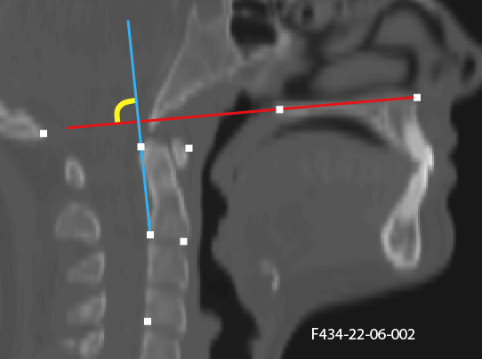
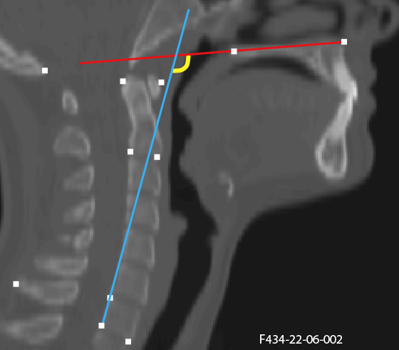
V8. C6-C4 angle
This variation of the lower cervical spine angle defines the posterior border by the posterior inferior of C6 (10) to the posterior inferior of C4 (8).
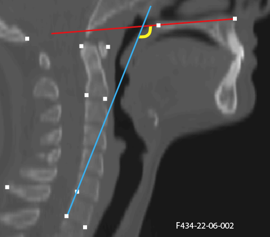
V9. C7 angle
This variation of the lower cervical spine angle defines the posterior border by the posterior inferior of C7 (11) to the posterior superior of C7 (12).
V10. C7-C6 angle
This variation of the lower cervical spine angle defines the posterior border by the posterior inferior of C7 (11) to the posterior inferior of C6 (10).
V11. C7-C5 angle
This variation of the lower cervical spine angle defines the posterior border by the posterior inferior of C7 (11) to the posterior inferior of C5 (9).
V12. C7-C4 angle
This variation of the lower cervical spine angle defines the posterior border by the posterior inferior of C7 (11) to the posterior inferior of C4 (8).
Upper and lower cervical spine difference
The change in angles along the cervical spine assist with determining the neck position. Following are multiple angle difference measures.
V13. C2 v C6-C4 difference
This measure calculates the difference between the C2 angle (V7) and the C6-C4 angle (V8).
V14. C2vC7 difference
This measure calculates the difference between the C2 angle (V7) and C7 angle (V9).
V15. C2vC7-C6 difference
This measure calculates the difference between the C2 angle (V7) and C7-C6 angle (V10).
V16. C2vC7-C5 difference
This measure calculates the difference between the C2 angle (V7) and C7-C5 angle (V11).
V17. C2vC7-C4 difference
This measure calculates the difference between the C2 angle (V7) and C7-C4 angle (V12).